A Quick Tour of ALS and ALS-U

The Dome structure used to house the 184-inch Cyclotron has become the home of the Synchrotron Radiation Source, aka the Advanced Light Source (ALS). The ALS is a type of particle accelerator known as a synchrotron that generates extremely bright beams of light ranging from infrared through X-rays. There are only a few dozen synchrotron light sources worldwide. The ALS’ light is directed through 40 highly specialized instruments called beamlines to experimental end stations, where scientists from around the world conduct simultaneous studies in fields ranging from materials science and biology to physics and chemistry. The facility is optimized for science conducted with lower-energy “soft” X-rays that have the ideal energy range to probe the chemical, electronic, and magnetic properties of materials.
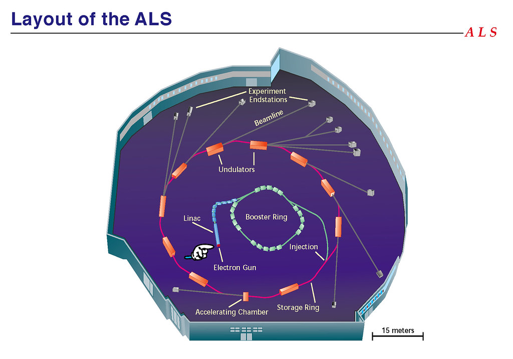
Footprint of the ALS, showing all the major components of the machine. Starting with the Electron Gun, that generates the electron bunches.
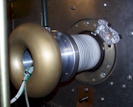
The Electron gun with its corona ring sitting at -125 kV deck
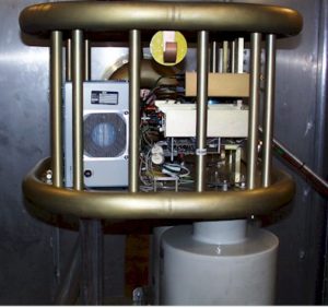
-125 kV gun deck with the gun system components. Fiber optics are used to transport all the control signals at ground level to the -125 kV deck.

Gun Socket
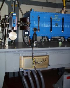
Master Trigger Generator
Mounted close-by of a booster magnet (blue). The magnetic
sensor is installed in the fringe field of the magnet.

The master trigger pulse activates the ALS timing system that provides synchronized timing signals around the entire machine including the experimental stations around the storage ring.
Block diagram showing the electron gun, the 125MHz and 500MHz sub harmonic buncher cavities and the two 3GHz linacs, the booster ring, the storage ring and beam lines for the experimental stations.
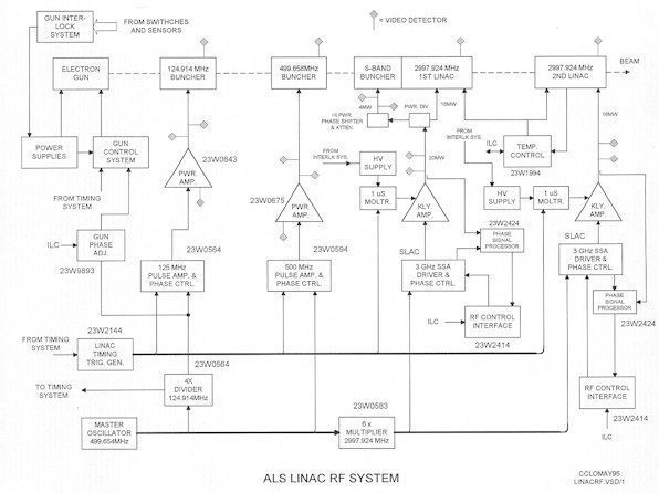
Block diagram showing the support systems for the electron gun, the subharmonic bunchers and the two linear accelerators
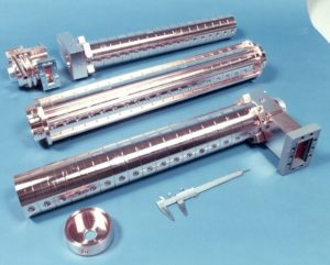
3GHz linear accelerator wave guide

Assembled Linear Accelerator
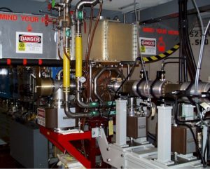
The single Booster ring 500MHz cavity boosts the energy of the electron beam before injecting it into the Storage Ring that has two 500MHz cavities for topping off and replenishing energy of the electron beam as it coasts around the Storage Ring.
Block diagram showing the RF support system for the two storage ring 500MHz cavities
300kW Klystron for powering the two Storage Ring 500MHz cavities. Arc detectors (two can be seen in the picture) are used to detect arcing inside the waveguides to shut down the high power Klystron preventing it from being damaged.
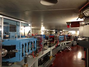
A section of the storage ring

A view of another section of the storage ring
Beam lines providing light source for various Experiments
From ALS to ALS-U, on-going 2022
For many experiments, the quality of the data collected depends on the number and regularity of light particles – known as photons – that can be concentrated in a small spot. The upgrade currently underway is intended to make the ALS the brightest storage ring-based source of soft X-rays in the world. The ALS-U project will replace the electron storage ring, the part of the accelerator where light is produced. The ALS’ X-rays are produced by electrons that race around a ring 200 meters (600 feet) in circumference at nearly the speed of light. Along the way, powerful magnets steer and focus the electron beam to keep it on its circular orbit, while additional magnets bend the beam, generating a broad spectrum of light that’s guided through beamlines. Better focus of the electron beam translates to better focus of the light produced and higher-quality data about the samples being studied. The new electron storage ring will leverage a next-generation magnet technology known as multi-bend achromats. Whereas today each one of the 12 arcs that make up the accelerator ring includes three bending magnets, after the upgrade each arc will include nine bending magnets, allowing for more precise steering and tighter focusing of the electrons. As a result, X-ray beams that today are about 100 microns (thousandths of a millimeter) across – smaller than the diameter of a human hair – will be squeezed down to just a few microns after the upgrade.
 ALS ALS-U
On the top part A of the above illustration, the left part shows the current ALS footprint whereas the right part shows the ALS(U) layout. The bottom part B is the current ALS magnets layout, and the right part shows the up-graded ALS(U) magnets arrangement.
The video clip illustrates how the electron bunches are being injected into the accumulator ring in a much orderly and controlled fashion so the resulting beam measures a few microns instead of 100 microns as shown below in the two photographs.
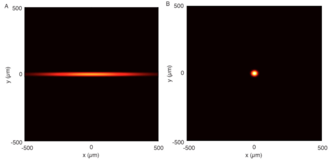
ALS beam profile ALS-U beam profile


